Here are 2 video tributes to John Bedini where he discusses Rife’s technology on the Jeff Rense show. Thanks to Davy Oneness for creating this video tribute!
The latest update on John Bedini’s knowledge regarding this technology is available at http://bedinirpxbook.com
Here is a short video with Tom Childs of TeslagenX and myself (Aaron Murakami) discussing what we are doing in the near future to continue the legacy of John Bedini’s work.
Al Francoeur has been involved with energy technologies since the 1980’s and is the inventor of several interference generators that operate with reduced back emf.
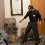
He is the owner of several E.V. Gray Motors that were later converted to run conventionally. There are some clues in these motors and an original power supply, which appears to have never been tampered with. Al has found a few clues as to the original operating method and will be sharing his perspective on these aspects of the Ed Gray Motor technology at the 2017 Energy Science & Technology Conference.
Mark McKay is a researcher that has traveled the country visiting Ed Gray’s family, friends, engineers, etc. and has revealed his historical findings in these presentations: http://evgrayrevealed.com/
Al’s presentation will be a perfect companion to Mark’s presentations and will be released after the upcoming conference.
Come meet Al Francoeur at the 2017 Energy Science & Technology Conference – there are only 8 seats remaining: http://energyscienceconference.com
Here is a video showing some of the things that are available for sale in a storage locker. Most is of course in boxes, but we’re showing what is out in the open first. We’ll get to the boxed up stuff later.
If you’re interested in anything that you can see, make an offer and email it to the email listed in the video.
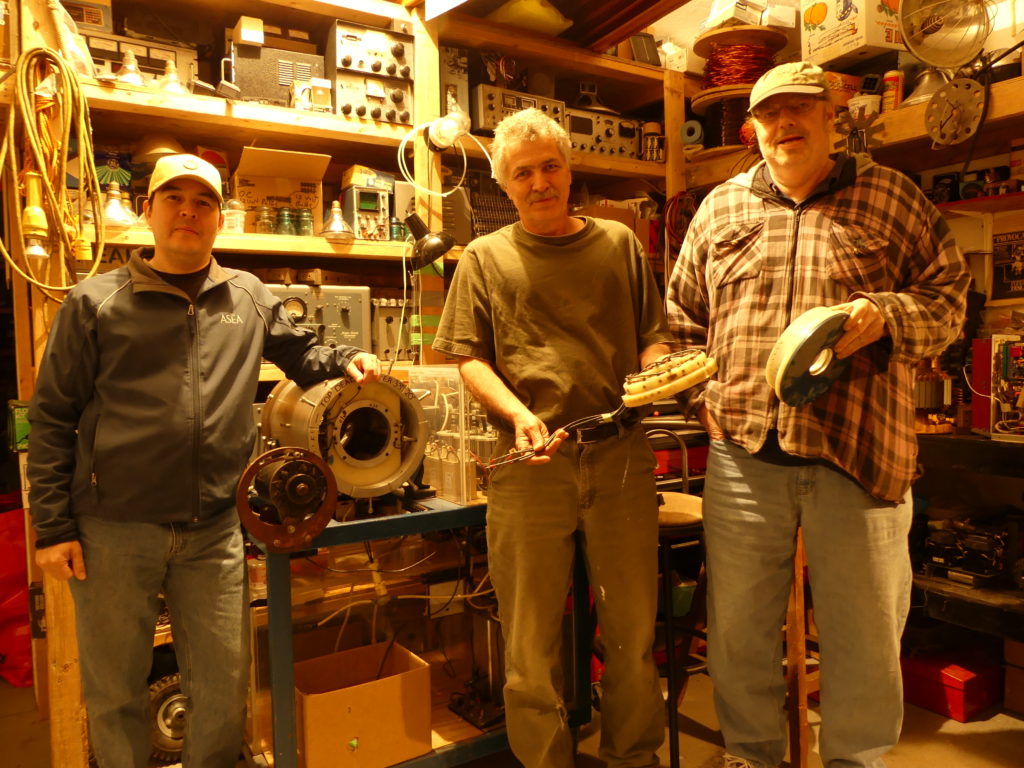
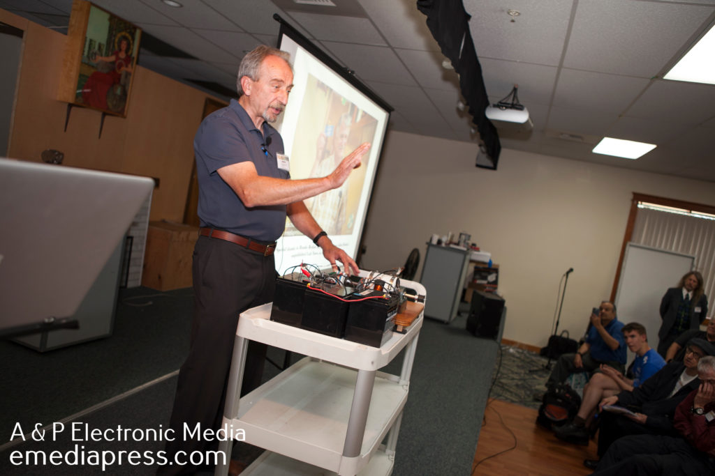
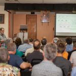
Yaro Stanchak made history at the 2017 Energy Science & Technology Conference by presenting the background history, John Bedini’s lab notes, and all other details necessary to replicate the Zero Force Motor.
The Zero Force Motor was one of John Bedini’s most coveted technologies and was instrumental in his early development of a magnetic model that influenced his work all the way to recent times.
This is a highly efficient motor that can go high speeds while drawing very little current. It also operates on some interesting principles that have most people scratching their heads.
This presentation is now available so you can have the most comprehensive collection of information on the Zero Force Motor that has ever been assembled.
Poor Man’s Split the Positive Battery Swapper by RS Stafford
At last year’s conference, Peter Lindemann demonstrated a Bedini SSG energizer that produced a lot of mechanical work all weekend and the batteries stayed charged up!
It worked beautifully and was done with an automated circuit that rotates the batteries in a certain way but most people do not have the know-how to be able to build that circuit.
At this year’s conference, RS Stafford replicated this battery swapping method with circuit breaks and other common parts from his local hardware store. It’s inexpensive and very, very simple to build. This is the machine that ANYONE can make work if they just follow some simple wiring diagrams and RS’s instructions.
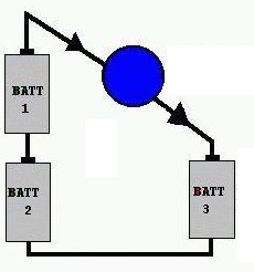
Let me explain the Split the Positive concept… lf I were to ask someone – even someone with a background in electronics or electricity if a light bulb would light up if it were placed between the positives of the batteries as shown to the left, they would say no.
Let’s say they are 1.5 volt AA batteries. The two in series makes 3 volts and the other single battery is 1.5 volts by itself. Well, 3 volts – 1.5 volts in opposition means there is still a voltage potential difference of 1.5 volts between the positives. A LED bulb for example will indeed light up because potential differences are what are important in electricity and NOT polarity.
Here’s an important thing to understand – while the bulb is lit up, the current from the two batteries in series is charging up battery #3. Therefore, if battery #3 is dead, it will charge up as the bulb is lit. When it is charged, it can move to the position of #1 or #1 batteries and one of the batteries #1 or #2 can be placed into the #3 position and it will get charged up while the bulb is lit. So you can see that by constantly rotating these batteries, you actually wind up with way more load powering capability than you would get if you just ran the bulb on a single battery until it’s dead and do that for the other two batteries.
John Bedini came up with this method years ago after studying the concepts in the famous Ed Gray motor, which had a similar process, but with much higher voltages. The above example has been known as Bedini’s 3 Battery system and very few people have ever understood the profound implications of it.
Now when you combine this concept with a highly efficient Bedini Energizer where you can recover a high percentage of what goes into the system in addition to getting some extra electricity from some generator coils that have very low drag, you have the keys to be able to produce mechanical or electrical work while making up for virtually all its own losses. That means you have a simple system that keeps itself charged up and you can create the battery swapping part of the system with parts from your local hardware store!
Our power grid is doomed to crash and you will be at a very strong advantage with what RS is teaching you here in this presentation.
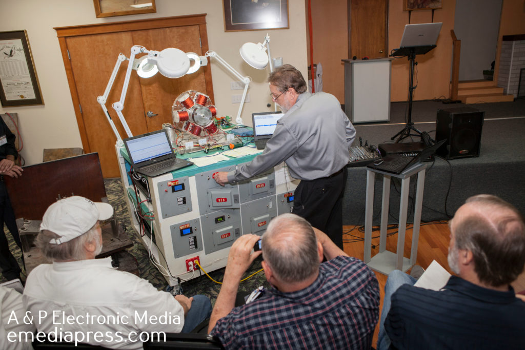
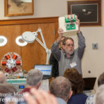
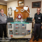
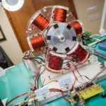
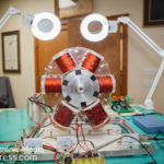
The Kromrey Generator is one of the most interesting generators that has made it to the public. Although it has never been mass produced, enough researchers and developers have built them to demonstrate that it definitely has some anomalous properties. John Bedini is one of those geniuses that has been involved with the Kromrey Generator before most have ever heard of it as well as having built many variations that hold up to the claims of the inventor.
At the 2016 Energy Science & Technology Conference, Peter Lindemann presented a large-scale Bedini SG that ran itself and kept its batteries charged up as well as demonstrating John’s 2 Pole larger Kromrey Generator. In the demonstration, it showed that the input motor drew about 32 watts while charging a battery with 72 watts. That is about twice as much output as what was being supplied to the input. Peter’s presentation that goes into the operation of this machine is available here titled Bedini SG – Beyond the Advanced Handbook – http://bedinisg.com
On that same website is the third SG book called Bedini SG – The Complete Advanced Handbook and that goes into a lot of the details on the Kromrey Generator as well.
Below is a video where I show a simple video of the machine actually speeding up as the output is shorted – normally, this would create so much counter-torque that it will make it very difficult for the input motor to turn. Instead, it actually climbs 50-60 rpm while the input power actually drops! There is a simple reason for this but there are other anomalous aspects that conventional science cannot explain such as the demonstration results that Peter showed at the conference. The below video also gives a few closeups of the Kromrey Generator that John Bedini built (one of them) as well as an error that I discovered in the Kromrey Generator patent that nobody has ever pointed out until now.
Make sure to register for the 2018 Energy Science & Technology Conference – you never know what we might show next! Energy Conference
Share this video with your friends with the share buttons below – not everyone has seen a generator that actually unloads the prime mover when it is shorted out! Please understand the significance of this machine is profound. Imagine a gas generator set running and you turn on some lights powered by the generator but the gas engine stays the same RPM. That means that it doesn’t take more electricity to power a load. I still consider this technology in its infancy and there is a lot of room for improvements, which may be coming out in the near future.
Here is Shorted Coils Part 2, which shows a couple benefits of why you would even want to do it, possibly, in some of your own builds. You wind up with more output from your coils while simultaneously unloading the prime mover. We’ll show a bit more on the Kromrey with a few more experiments in another video soon:
Share this with the buttons below and register at the 2018 Energy Science & Technology conference here: Energy Conference
Recently, I purchased two of the motors myself and will rewind one so I can have a pulsed motor to run the Kromrey Generator. It has a regular steady DC motor and I was going to put a Zero Force Motor on it, but because of the lack of time, the Matt Motor Modification is the most practical way to quick results.
After you watch Matt’s videos, the above picture will make sense. Make sure to read this entire thread, but to get a jump start on results, read the thread from early December of last year until now. You’ll see some images I posted and I’ll be reporting my results and will post videos to show that what Matt has taught everyone it can be replicated, it’s inexpensive and relatively simple.
Please join http://energeticforum.com and share your work on this project. It helps everyone and encourages others to get started. Share this with the links below!
There have already been a few posts/videos on shorting coils and they’re relationship to the Kromrey Generator. To show the potential, no pun intended, of shorting the Kromrey Generator coils, another video is available.
You can see that over 700 volts AC is available by shorting it’s small generator coils or almost 600 volts DC from the same coils.
Get Peter Lindemann’s presentation on the Kromrey Generator here: http://bedinisg.com
Geoffrey Miller recently shared a few tidbits about the Missing 1984 presentation by John Bedini. Here is the interview with a few pics from the presentation that will give you a glimpse into what is coming out soon!
This is a * MUST HAVE * video that is not only historical and RARE as hen’s teeth, it is highly valuable and the material that John covers is absolutely priceless. You will see John Bedini in a completely unrestrained form unlike anything you have ever seen from him. He holds back on nothing and is completely forward and blunt about each and every claim he makes.
Zero Force Motor Part 2 – Hidden Dance by Yaro Stanchak
At the 2018 Energy Science & Technology Conference, more revelations are disclosed about the last one year of experiments with the Zero Force Motor.
Within this follow up presentation, you will find all the specs, which should be considered a standard built for more experiments to get start with. It works and has already been proven out by Yaro Stanchak and James McDonald.
Yaro also shares the differences in more detail on attractive vs repulsive mode and how this looks diagrammatically so the viewer can benefit from these findings. A thorough walk-through on the Zero Force Motor’s timing characteristics of the magnet’s geometry in relation to the coil geometry is covered. This is very important and cannot be stated enough – timing is crucial and can make or break your results.
Get 25% off for a limited time with this coupon: ZFM25
Keep in mind this is a developmental process and there are no free energy claims. It is a novel motor with unique aspects that have not been used or exploited in conventional motors and bit by bit, the potential of what this machine is capable of is slowly revealing itself.
Pay close attention to the date in the table presented by Yaro. You may find there is more than meets the eye. And you will definitely see that at certain RPMs, which may indicate some resonant points that you will see the Hidden Dance happening within the machine as Yaro shows on the scope.
There is also a difference in the characteristics of how the motor operates in relation to its waveforms that are measurable if the ZFM is running on a battery compared to a linear current power supply. In other words, there appears to be advantages to running it on a battery compared to a power supply. Professor Robert Haralick during questions points out a very plausible reason for this and that is that when running, the ZFM is producing longitudinal waves that are accepted by the battery(s) but the linear amp power supply cannot.
This would be completely consistent with John Bedini’s experience over the years with experiments on the Bedini SG when running on and charging batteries, which have shown unusual input vs output ratios and most of this disappears when running these machines on conventional power supplies. It has been stated over the years that the battery is very important as part of the open system and once again, these ZFM experiments shown by Yaro seem to indicate the same results.
Here are a few of the subjects that Yaro will show in this presentation:
Introduction and Brief Review Of Zero Force Motor Design and Operation
The Self-Recharging Battery Supply of Carlos F. Benitez by Peter Lindemann, D.Sc.
NOTE: This machine was demonstrated at the 2018 Energy Science & Technology Conference (ESTC) but there was no formal presentation. It was only explained to attendees who were interested enough to ask Peter Lindemann questions about it back in the vendor/demo room. This machine is a very small powered demonstration, but proves the point and kept itself charged up all weekend while running a motor/generator. This EXACT circuit from 100 years ago is the foundation for several well-known circuits that have been taught by John Bedini and others over the years – you are being handed the origin of where much of it came from.
Between 1915 and 1918, Carlos F. Benitez was issued 4 British Patents on a “System for the Generation of Electric Currents.” It was the early days of the “electrical era” and many experimenters were claiming new ways to produce useful electrical effects. But this was different. Benitez was claiming to be able to run light bulbs and motors from batteries that never needed to be re-charged from a conventional, external source.
By this time, the Laws of Thermodynamics had become widely taught, and so most electrical engineers did not take these claims seriously. Even today, 99% of scientists and engineers believe this is impossible, under any circumstances.
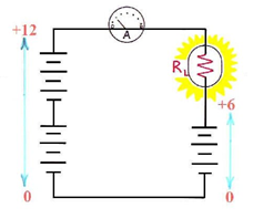
Here’s why: Classic electrical theory assumes that when a load is operated in the manner shown here, the load RL receives ½ of the power provided by the 12 volt supply, and the 6 volt battery wired in reverse receives the other half as a charging effect. Since the battery being charged only receives ½ of the energy supplied by the source, rotating the batteries back and forth runs them all down in a conventional manner.
So, it is curious to find this quote in one of Benitez’s Patents:
“Obviously the current furnished by the discharge of battery 1-2 alone, would produce a smaller charge in batteries 3-4, if some extra energy were not added to the normal output of said battery 1-2. With this object in view any of the known methods for the generation of high frequency currents, as well as those described in the aforementioned English Patents, can be employed in conjunction with said batteries, in order to provide that complementary energy, and in this manner it is always possible to charge and discharge alternately each battery from one to the other, maintaining constant a storage of electricity and producing furthermore an excess of electrical energy.”
On the Patents, Benitez is referred to as a civil engineer, living in Guadalajara, Mexico. So, while he may not have been earning his living in the electrical sciences, he certainly was familiar with both classic electrical theory and the benefits of his discoveries!
For any honest student, the questions become: Was Benitez mistaken, or did he discover something important? And if so, HOW is this possible??
Benitez was issued 4 Patents, and each one describes a different circuitry and method to accomplish the objects of the invention, which included running external loads AND returning the electrical source to its initial state of charge simultaneously. Since there was no dispute about how much energy was being dissipated by running the loads, the following conclusion may be drawn:
Benitez discovered that it was possible to return a battery to a higher energy state with fewer watt-hours delivered to it than classic electrical theory would predict, as long as that energy was applied to the battery under the correct conditions and in the proper manner.
Today, we would describe this as the ability to charge a battery at a COP > 1.
As John Bedini always said, the “gain” showed up in the battery. The circuits themselves always operated at an efficiency below 100%.
If we assume that in the circuits that had two banks of batteries in them, the charging batteries were receiving about ½ of the energy provided by the run batteries, then the circuitry had to overcome the loss of running the loads and the loss of running the circuitry itself. In this instance, the system would have to be able to produce a charging effect in the receiving batteries equal to 2.2 times the watt-hours provided, or a charging COP > 2.2 for the system to self-sustain indefinitely.
So, the GOAL for an operating system is to attain a battery charging efficiency with a COP > 2.2!
That said, there are other ways to accomplish the goals of the invention, but “super-efficient” battery charging is definitely one of the ways. For students familiar with the work of John Bedini, this method is the best documented and published on, as well.
NOTE: This presentation gives you the EXACT schematic to replicate Peter Lindemann’s circuit that he demonstrated at the 2018 ESTC, operating theory, supporting diagrams and complete explanations of how to operate it. Also, there are multiple URL shortcuts inside the zip file that are highly relevant to this technology. Some are to other presentations and some are to specific discussions at Energetic Forum.
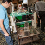
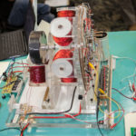
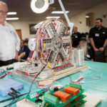
RS Stafford is a long time researcher in the energy sciences and knows more about John Bedini’s work than most. He is blessed to have been able to acquire John Bedini’s 6 coiler SG and the large Ferris Wheel Motor.
Here is the goal and why we need your help to raise some donations:
Investigate John Bedini’s Ferris Wheel Hub Motor and Mag amp Motor to get a better handle on how this Tech works. Map out the Magnetic Fields around the various magnets and coils. Document and study all the various values of the components. Add extra Energy producing equipment to demonstrate various concepts that John Bedini has shown us.. And to show case experiments beyond what JB was allowed to show us. Then Bring the Ferris Wheel to the 2020 Energy Science & Technology Conference for a full Presentation.
The below is an excerpt from the full length vendors & announcement videos from the 2019 ESTC.
John Bedini’s Self-Recharging Motor by Peter Lindemann, DSc
Last year, Peter Lindemann demonstrated a self-recharging system invented by Carlos Benitez, which is the apparent origin of self-recharging battery systems.
This year, Peter demonstrated a method John Bedini used to keep a battery bank charged up while running his monopole motors. The method had been mentioned in the past in online forums, but nobody seemed interested enough to actually explore the reality to it.
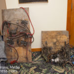
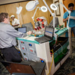
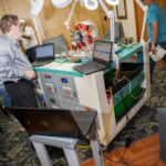
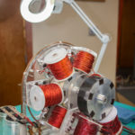
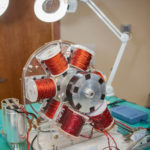
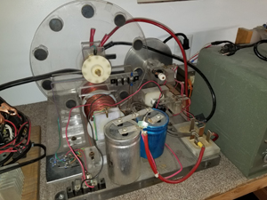
I personally witnessed this method nearly 20 years ago at one of John’s shops affectionately nicknamed the “Palace” because of its interesting interior layout. Below is a picture of the EXACT machine that John Bedini accomplished this with. I also include a 12 minute video where I show you the machine in a video and give a basic explanation of the self-recharging process.
It was done most often with a plexiglass rotor where the coils were on both sides of the face of the rotor rather than at the circumference. It charged a large cap bank, which was then discharged to output bank. A battery was then shuttled back and forth between the front and back indefinitely without ever having to place them on a regular charger to charge them up since the machine and its setup accomplished this.
This demonstration unit that Peter showed kept its battery bank charged up all throughout the conference one one single charge. During the presentation, the monopole is running and he describes how the battery bank is arranged.
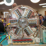
In 1999, when John Bedini was first introduced to me, this “Glass Case Motor” was the first thing he wanted to show me so it had always been very special to me but it was even more special to John. It is a beautiful work of art that John built because it embodied the many principles that were worked out over the years with his partner from the past, Ron Cole.
The first time he ever presented it publicly was at the 2015 Energy Science & Technology Conference but it was mostly a demonstration along with the history and some of the thinking behind it but he never disclosed the circuit specs, coil details, etc.
The interesting or even profound thing about this “glass case motor”, which John actually called the Gravity Wave Space Flux Motor, is that it had run countless hours over the years on 30 year old either alkaline or zinc carbon batteries. The batteries had been seen to be in such poor shape that they were practically falling apart but nevertheless, once the rotor is spun, it picks up speed, turns a propeller shaft with eddy currents, blinks LEDs but the batteries never seem to die.
The long-awaited, full-disclosure that everyone has wanted but never thought would happen is coming to the 2020 Energy Science & Technology Conference.
While we may not be able to claim we know all the answer as to why this particular arrangement of coils, magnets, etc. can demonstrate these amazing feats and we may not be able to claim that we see this motor the same way John did as he had his own unique way of looking at things, you will will walk away with all the information necessary to replicate this historical and amazing machine!
Get your ticket now while you can for our 9th annual event – 2020 Energy Science & Technology Conference – register now: 2020 Energy Conference
NEW FREE VIDEO WITH BATTERY & SOLAR SECRETS ON YOUTUBE
This is not a promo video sell these solar charge controllers because all the inventory was sold and we’re not producing any more anytime soon. It is to help those that already purchased a S3A12 but that’s not all – you will greatly benefit from this information. Read every bullet point of what is covered in this video.
How to properly hookup and use the S3A12, why the Green light comes on before it is topped
How to properly calculate safe discharges from lead acid batteries
Why the claim that crystalline panels are more efficient than amorphous has no real meaning and why
What the VMP and other specs on the panel means and which ones you need to pay attention to the most
Description of the true topping event so you know the battery chemistry has been reversed to like-new condition
A bit about how to restore some battery life
Why batteries sitting on concrete go bad – it has nothing to do with the concrete
How to use a constant voltage / constant current power supply to imitate a solar panel for testing
Why every solar generator manufacturer or kit supplier are ripping you off with their inverters
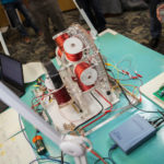
It’s very exciting to finally release version 3.0 of the most authentic Rife Frequency generator manufactured anywhere in the world. The link at the end of this sentence titled “Rife Machine” takes you to the Vril.io RPX page that explains why that is true – scroll back up to this link but read this page first: Rife Machine
Below is a sneak peak at the Bedini RPX 3.1MHz Sideband Generator v3.0 – “Rife Machine”. If you’re not familiar with what a sideband generator is, the above link will take you to a page that explains it. Any machine that correctly produces “Rife Frequencies” the way that Rife and his assistant Philip Hoyland did must be done with “sidebands” or it is not a Rife Machine – this is an indisputable, historically-documented fact.
RPX stands for Rife, Priore and an X-Factor but it really should stand for Rife, Priore and Bedini because what his genius incorporated into the RPX is in fact the X-Factor. When we release the v3.0, you’ll learn why the RPX is far superior to any other device even remotely similar and there is only one that is close that I know of and that John Bedini truly was the world’s leading authority on what Rife was doing.
First, here’s a picture of the original unit – it worked perfect but was a bit cumbersome since you have to connect an external signal generator and external battery but this is how John Bedini originally released it late 2014 or early 2015. Below, you’ll see the obvious point to the new RPX 3.0 and why my goal was to make the most user friendly “Rife Machine” ever developed and it has been successfully accomplished.
Below you can see the prototype (no logo or labels for the knobs, switches or jacks). The signal generator inside was designed by Paul Babcock so this couldn’t have happened without his brilliant help. Others were kind enough to offer their services to design one in the past but at that time, the cost was prohibitive, plus, I wanted to stay away from digital as much as possible because digital is fake and analog is of the real world. THE SIGNAL GENERATOR IS 100% ANALOG. Both Rife and Bedini would be thrilled about that!
The LEFT KNOB controls the TIME of the sweep. Specifics will be forthcoming.
The SWITCH between the knobs in the down position leaves it in WIDEBAND MODE so it sweeps from close to 0Hz up to 150kHz to create sidebands that are all even multiples of EVERY SINGLE Rife Frequency automatically without having to. Rife went to 40kHz because that was the upper range of a typical audio signal generator. Why go to 150kHz? It’s one of the things that makes this superior to any sideband generator that creates the Rife Frequencies and I’ll show the math and demonstrations for this so you understand what this means and why it is important. What did Bedini know that Rife and Hoyland possibly didn’t? You’ll find out soon on the page where these units will be available for pre-order on February 17th, 2022.
The RIGHT KNOB controls the narrow band sweep. When the switch is in the up position, it activates the narrow band mode. I’m asked all the time about focusing on certain frequencies. It’s always a bad idea to use any single static frequency as a “wobble” or variation in the frequency was always what was found to be superior. So within the 150kHz range, the narrow band will focus on a 25-30kHz range. If the knob is all the counterclockwise, it will sweep from almost 0Hz up to about 25kHz and as you rotate the dial clockwise, it will keep a 25-30kHz sweep width but higher up in the 150kHz range. There will be a chart printed on top of the case that shows you what frequency range you are at based on the number on the dial, which will be printed on the front panel.
Scroll down to the top of the next picture for an explanation of the rest of the features on the front panel – I just want to break up the text a bit to make it easier to read.
The switch at the top next to the gold RCA jack allows you to use the internal signal generator, which is all anyone will need 99.99% of the time. In the down position, you will be using the internal signal generator and the two knobs and switch to the left. But for those of you who are more technically oriented, you can move the switch in the up position and you can then plug in your own signal generator into that RCA jack. ONLY USE SINE WAVE AND LIMIT THE OUTPUT VOLTAGE OF YOUR SIGNAL GENERATOR TO 2 VOLTS MAX or you can damage the unit. You will able to narrow the sweep to perhaps a few kilocycles on either side of a target frequency to get more specific, extend sweep times beyond what is possible with the internal signal generator or even use frequencies that will produce sidebands that are even multiples of frequencies like 432Hz or any other frequency set of numbers using this method. We’ll teach you how to calculate all that with videos that will be available.
The RED and BLACK banana jacks at the bottom are the output jacks. We supply a cable that you can plug into that and on the other end are alligator clips. You only have to supply your own electrodes. Inexpensive copper tubing from a hardware store than you can get for a few dollars per foot is all you need. Two pieces about 4″ long and maybe 3/8 to 1/2″ diameter is sufficient. Conductive gel is recommended and this one is the only one I could easily find that is free of parabens – this is our Amazon affiliate link: Conductive Gel
If you’re mechanically inclined, we’d recommend cutting off the alligator clips and soldering the wires to the tubes or adding ring terminals and screwing them to the tubes. Later on, we may recommend a company where you can get some electrodes.
The top right LED light is a RED power light that shows the RPX power is turned on (switch is on the back).
The LED directly under that shows when the PUMPWAVE is on and it will also be RED – just the prototype has the blue light and its just too bright. The switch underneath that can be switched to turn the Pumpwave off and on. This is another one John Bedini’s genius innovations. With the switch off, you can still get the classic Rife Frequencies with the 3.1MHz carrier and sidebands. With the switch on, you get the low frequency carrier (another carrier) that puts the 3.1MHz carrier and sidebands on it and that Pumpwave is a 8-9Hz square wave that takes electrode delivery to another level. Literally, there is nothing that compares to the Bedini 3.1MHz Sideband Generator v3.0.
Above the next picture is a description of what is on the back of the RPX.
The jack and switch below will be flush with the panel on the final units. The jack on the left is for a 16.8 volt 1 amp, regulated lithium-ion charger. The red light on the charger will be on while it is charging and when it is finished charging, the green light will come on. You will not be able to use the RPX while the battery is charging – plugging in the charger will disconnect the battery from the circuit. Please charge the battery fully before using the RPX for the first time. The average use time the RPX is on is about 15 to 30 minutes so you will get a good number of uses before you have to charge the battery again. The switch on the right is the off/on switch to turn on the power. In the down position, it will be off and in the up position, it will be on.
I’ll make a video walk thru and will put that on the RPX page when pre-orders are open on February 17th along with pricing, etc.
The RPX v2.0 model sold for $425 itself (required you to provide your own battery and signal generator) or $650 for the whole combo kit that included everything except the electrodes. My goal was to make this new RPX 3.0 available for as close to the RPX v2.0 price as possible. The RPX v3.0 will cost more because my production costs are higher. The first 50 (most likely 50) units for pre-sale will be at a super low price compared to what the retail price should be.
Keep in mind that the next closest machine that even comes close to a “Rife Machine” retails for over $1800. That means that since this is a superior technology and it is a super specialty item not available anywhere else that the RPX v3.0 should have a retail price of around $2000 to $2500 (but it won’t be) and it would be worth ever penny comparing value vs value in terms of sale price.
Make sure to order as soon as the pre-order page opens up on February 17th because you’ll be pleasantly surprised with our pricing! You’ll also be earning points on emediapress.com that is good for credit toward digital downloads. More to come…
Remember to go to this page to learn more in depth about the truth about what a Rife Rife machine is and what it isn’t’: Rife Machine
Special thanks to Simon Davies aka dR-Green (on Energetic Forum) for creating a simple, user-friendly calculator on the new RPX website. Everyone can instantly see what audio frequency needs to be mixed with the 3.1 MHz carrier in order to create sidebands that are rich in harmonics for ANY frequency they want.
Simon has been replicating much of Tesla and Dollard’s work over the years and his calculators are accurate so if you want to know how to calculate windings and other parameters for your experiments, he has both free and paid calculators available at: Tesla Scientific
Here’s an example of how you can use this calculator and the RPX as a 432 Hz harmonic generator, which nobody else is doing.
You take the carrier of 3.1 Mhz and divide it by 432 = 7175.93
Round up or down to the nearest whole number = 7176
Multiply your desired frequency of 432 x 7176 the multiplier = 3.100032 Mhz sideband that will be created
The difference between the sideband and carrier is 32 Hz
Therefore, if you use an external signal generator with the RPX and you input a sinewave limited to 2 volts with a frequency of 32 Hz, it will create a sideband of 3.100032 MHz, which is a multiple of 432 Hz and it will have a whole lot of harmonics of that frequency.
This can obviously be done with any desired frequency – why not use Rife’s brilliant method to create frequencies for your frequency needs? Everyone else is just focusing on the fundamental frequency but are completely ignoring the fact that the real power comes from all the harmonics.
Go to the calculator here, enter the desired frequency and hit return. You’ll instantly get the audio frequency needed to be input into the RPX to do the above: https://emediapress.com/rpx3#resources


 Let me explain the Split the Positive concept… lf I were to ask someone – even someone with a background in electronics or electricity if a light bulb would light up if it were placed between the positives of the batteries as shown to the left, they would say no.
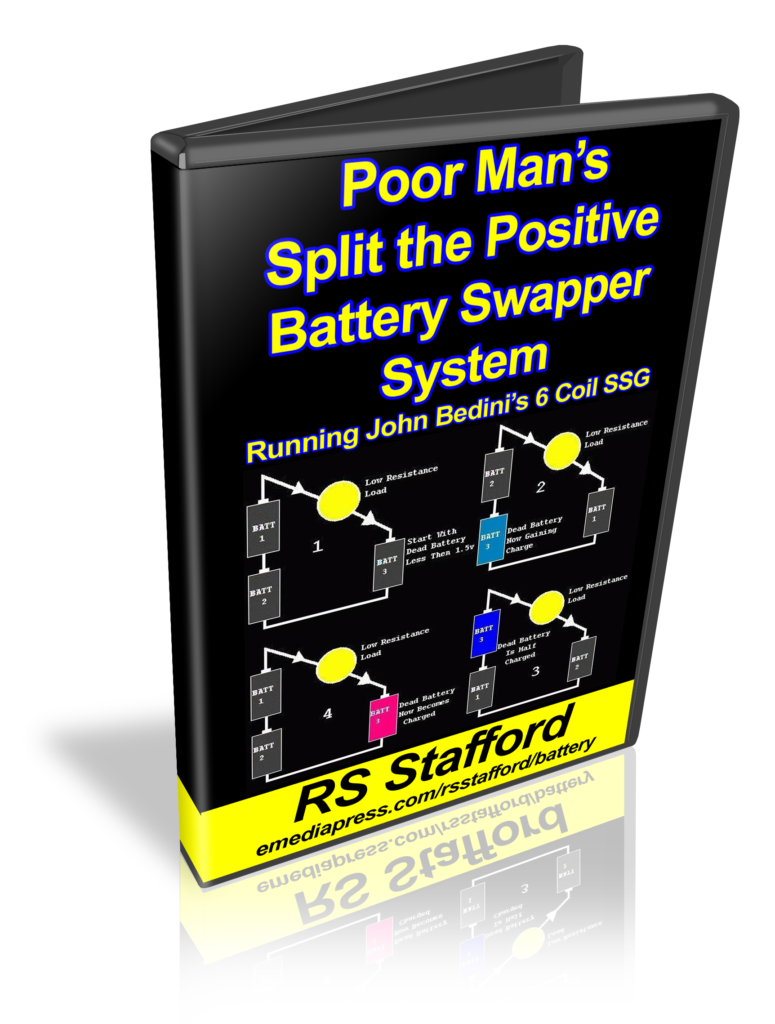


 By this time, the Laws of Thermodynamics had become widely taught, and so most electrical engineers did not take these claims seriously. Even today, 99% of scientists and engineers believe this is impossible, under any circumstances.
 It was done most often with a plexiglass rotor where the coils were on both sides of the face of the rotor rather than at the circumference. It charged a large cap bank, which was then discharged to output bank. A battery was then shuttled back and forth between the front and back indefinitely without ever having to place them on a regular charger to charge them up since the machine and its setup accomplished this.


